MOTOR PRINCIPLE:
An electric motor is a machine which converts electric energy into mechanical energy. Its action is based on the principle that when a current-carrying conductor is placed in a magnetic field, it experiences a mechanical force whose direction is given by Fleming’s Left Hand rule (Fig. 1) and magnitude by the formula:
F (force) = Hil/10 dynes, where
H is the field between two magnetic poles
l is the length of the conductor and
i is the current carried by it
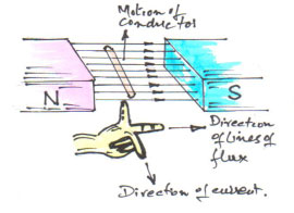
Fig. 1 showing principle of electromagnetic induction & Fleming's LH Rule.
Constructionally, there is no basic difference between a dc generator and a dc motor. In fact, the same dc machine can be used interchangeably as a generator or a motor. Just like generators, dc motors are shunt wound or series wound or compound wound.
In a multi-polar dc motor Fig. 2, when its field magnets are excited and its armature conductors are supplied with current from the supply mains, they experience a force, akin to driving torque, which sets the armature rotating.
The function of commutator in the motor is the same as in a generator. It helps to develop a continuous and unidirectional torque by reversing current in each conductor as it passes through from one pole to another.
Practical dc motor consists of Magnetic frame or yoke, field poles and pole shoes, field winding comprising pole coils or field coils, armature core, armature windings or conductors, commutator, brushes and bearings.
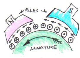
Fig. 2 showing part of a multi-polar motor.
Of these, the yoke, the pole cores, armature core and air gap between the poles and the armature core form the magnetic circuit whereas the rest form the electrical circuit.
SIGNIFICANCE OF THE BACK E.M.F.:
When the motor armature rotates, the conductors also rotate and hence cut the flux (magnetic line of force). In accordance with the laws of electromagnetic induction, e.m.f. is induced in them, whose direction is in opposition to applied voltage. Because of its opposing direction, it is referred to as back e.m.f, Eb. Figure 3 below gives the equivalent circuit of the motor.
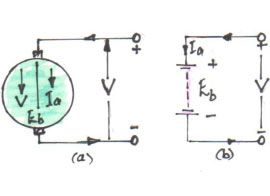
Fig. 3 showing equivalent circuit.
The rotating armature generating back e.m.f. is like a battery of e.m.f. Eb put across supply of mains of V volts. Obviously voltage V has to drive Ia against the opposition of Eb. The power required to overcome this opposition is Eb Ia. This is the power which is converted into mechanical energy.
As can be seen from the equivalent circuit (Fig. 3) Ia = Net voltage/Resistance = (V – Eb)/Ra, where Ra is the resistance of the armature circuit.
Also Eb = (ΦZN/60) x (P/A) x 10 -8 V, where
- Φ = Flux/pole in lines
- Z = Total number of armature conductors
- N = Armature rotation speed in rpm
- P = No. of poles
- A = No. of parallel paths in armature
Normally, for wave-wound armature, A = 2 and for lap-wound armature A = P i.e. the same as number of poles.
Back e.m.f. depends, besides other factors, upon armature speed. If speed is high, Eb is large, hence armature current is small. If speed is less, then Eb is less, hence more current flows which develops more torque. So, Eb acts like a governor, in that, it makes a motor self-regulating so that it draws as much current as is necessary.
VOLTAGE EQUATION:
The voltage V applied across the motor armature has to overcome
a) back e.m.f. Eb!
b) armature ohmic drop IaRa
Therefore, V = Eb + IaRa – This is called the voltage equation.
If we multiply both sides of the equation by Ia, we get
V Ia = Eb Ia + Ia2Ra – This indicates that
V Ia = Electrical input to the armature
Eb Ia = Electrical equivalent of mechanical power Pm developed in the armature
Ia2Ra = Copper loss in the armature.
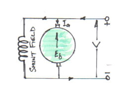
Fig. 4 showing shunt field
CONDITION FOR MAXIMUM POWER:
Re-arranging equation V Ia = Eb Ia + Ia2Ra in terms of mechanical power, we get
Pm = V Ia – Ia2Ra
Differentiating both sides with respect Ia and equating to zero, we get dPm / d Ia = V – 2 IaRa = 0, from which we get IaRa = V/2 and as V = Eb x IaRa and IaRa = V/2 Therefore Eb = V/2.
Thus mechanical power developed by a motor is maximum when back e.m.f. is equal to half the applied voltage. This condition is not realised in practice, because in that case current would be much beyond the normal current of the motor.
ARMATURE TORQUE OF A MOTOR:
If T is the torque in lb-ft developed by the armature of a motor running at N rpm, then
Work done/min. = T x 2πN ft-lbs
Therefore Power in HP = (T x 2πN/33000)
We know electrical equivalent of mechanical power in the armature = Eb Ia Watts.
Therefore HP developed = Eb Ia /746
Hence we have (T x 2πN/33000) = Eb Ia /746, but
Eb = (ΦZN/60) x (P/A) x 10 -8 V
Therefore, (T x 2πN/33000) = [(ΦZN/60) x (P/A) x 10 -8] x (Ia /746)
Therefore, T = [(33000 x 10 -8) / (2π60 x 746) x (ΦZ Ia) P/A]
Therefore, T = [0.118 x 10 -8 x ΦZ Ia (P/A)] lb-ft
In SI units torque T = [0.159 x 10 -8 x ΦZ Ia (P/A)] Nm
From above equation of torque, we have seen T ∞ Φ Ia, so that
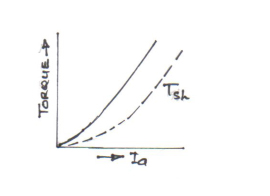
a) in the case of series wound motors, Φ is directly proportional to Ia (before saturation) because fieldwindings carry full armature current; therefore
T ∞ Ia2.
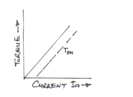
b) in the case shunt wound motor, Φ is practically constant, hence
T ∞ Ia
Also we know (T x 2πN/33000) = Eb Ia /746.
Therefore T = [(33000/2π x 746) x (Eb Ia / N)]
Therefore, T = 7.04 x (Eb Ia / N) lb-ft
SHAFT TORQUE, Tsh:
The whole of the armature torque, as calculated above, is not available for doing useful work, because certain percentage of it is required for supplying iron and friction losses.
The torque which is available for doing useful work is known as shaft torque Tsh and the power corresponding this torque is called brake horse power (BHP). Both of these quantities are related by formula:
BHP = Tsh x 2πN/33000 or
Tsh = 33000 x BHP/2πN lb-ft = 5252 x BHP/N lb-ft or
In terms of SI units,
Tsh = 9550 x kW/N Nm
Note 1HP = 746Watts.
The difference, T – Tsh, is known as lost torque.
Therefore lost torque, T – Tsh = 7.04 x (Iron & Friction Losses / N)
SPEED OF A DC MOTOR:
From the voltage equation, V = Eb + IaRa, we have Eb = V – IaRa
Also Eb = (ΦZN/60) x (P/A) x 10 -8 V,
Therefore, (ΦZN/60) x (P/A) x 10 -8 = V – IaRa
Therefore N = (V – IaRa/Φ) x (60A/PZ) x 108 rpm, since Eb = V – IaRa,
Therefore N = (Eb/Φ) x (60A/PZ) x 108 rpm or
N = k Eb/Φ
It shows that speed is directly proportional to back e.m.f. Eb and inversely proportional to the flux Φ.
For Series Motor
Let in the 1st case speed = N1, Ia1 = armature current and Φ1 = flux/pole and
Let in the 2nd case speed = N2, Ia2 = armature current and Φ2 = flux/pole, then
Using the relations whereby
N1 ∞ Eb1/ Φ1, where Eb1 = V – Ia1Ra
N2 ∞ Eb2/ Φ2, where Eb2 = V – Ia2Ra
Diving 2nd by 1st we get
N2/ N1 = (Eb2 x Φ1)/ (Eb1 x Φ2)
Prior to saturation of magnetic poles, since Φ ∞ Ia, we have
N2/ N1 = (Eb2 x Ia1)/ (Eb1 x Ia2)
For Shunt Motor
In this case the same equation applies i.e.
N2/ N1 = (Eb2 x Φ1)/ (Eb1 x Φ2) but if Φ2 = Φ1, then
N2/ N1 = Eb2 / Eb1
SPEED REGULATION:
The term speed regulation refers to the change in speed of a motor with change in applied load torque, other conditions remaining constant. By change in speed here means the change which occurs under these conditions due to inherent properties of the motor itself and not those changes which are affected through manipulation of rheostats or other speed controlling devices.
The speed regulation is defined as the change in speed when the load on the motor is reduced from rated load to zero, expressed a percent of the rated speed.
Therefore,
% speed regulation = (No Load Speed – Full Load Speed / Full Load Speed) x 100.
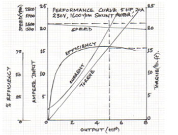
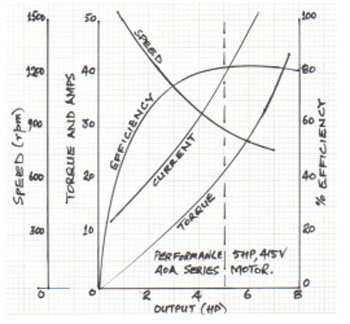
MOTOR CHARACTERISTICS:
The characteristic curves of a motor are those characteristics which show relationship between the following quantities:
a) Torque and armature current i.e. T / Iacharacteristic, also known as electrical characteristic.
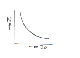
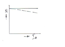
b) Speed and armature current i.e. N / Ia characteristic.
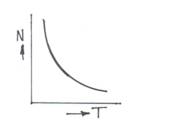
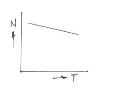
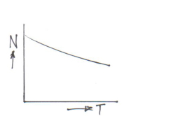
c) Speed and torque i.e. N / T characteristic, also known as mechanical characteristic.
While discussing characteristics, following relationships should be remembered
T ∞ Φ Ia and N ∞ Eb/Φ.